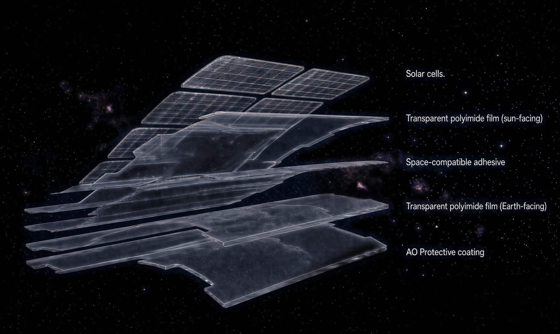
Bifacia™ is a high-performance colorless polyimide film engineered as a direct drop-in replacement for traditional amber PI substrates. It matches mechanical strength and environmental resistance while enabling bifacial power gain and cooler solar-cell operation.
A direct material substitution with system-level gains.
Bifacia™ preserves the role of a conventional polyimide substrate in the manufacturing stack while removing the optical and thermal penalties of amber PI.
Drop-in replacement
Colorless PI easily replaces traditional amber PI while maintaining comparable mechanical strength and environmental resistance. It is compatible with existing manufacturing processes, with no redesign or revalidation of core assembly steps required.
Up to 23% more power
Bifacia™ enables bifacial cells to use both direct sunlight and Earth-reflected light. Under typical LEO conditions, this can produce up to 23% more energy than equivalent monofacial panels.
Up to 10°C cooler operation
Colorless PI absorbs less solar heat than amber PI. Cell temperature can be reduced by up to 10°C, supporting higher conversion efficiency, lower thermal stress, and improved long-term reliability.
Layer stack
Light in from both sides.
How Bifacia Works
Open the rear side of the cell to Earth-reflected light.
Instead of showing product comparison photos on the website, this model explains the system effect directly. The transparent Bifacia™ layer lets rear-side irradiance reach a bifacial cell while retaining the structural role of a polyimide substrate.
Direct sunlightFront-side capture
Bifacial solar cells
Bifacia™ transparent substrate≥ 90% transmittance
Earth-reflected lightRear-side capture
Technical Data
Bifacia™ Technical Specifications
Typical values from the current Bifacia™ information sheet. Final acceptance criteria may be defined by mission requirements and applicable standards.
For the complete two-page product overview, technical table, orbital case data, and delivery details, download the current Bifacia™ data sheet.
Optical access
≥ 90% transmittance supports rear-side irradiance for bifacial solar-cell architectures.
Flexible construction
A bending radius below 20 mm across 100,000 cycles supports repeated flex evaluation.
Space-relevant screening
Low outgassing targets and orbit-specific environmental indicators frame qualification planning.
#
Parameter
Specification
1
Areal Density (at 250 µm thick)
< 300 g/m², tolerance ≤ 3%
2
Transmittance
≥ 90%
3
TML (Total Mass Loss)
< 1%
4
CVCM (Collected Volatile Condensable Material)
< 0.1%
5
Glass Transition Temperature (Tg)
≥ 120°C
6
Adhesion Strength
≥ 1 N/mm
7
Bending Radius
< 20 mm, 100,000 cycles
8
Insulation Resistance
≥ 10 MΩ @ 500 V
9
Coefficient of Thermal Expansion (CTE)
5–20 ppm/°C
10
Environmental Indicators
AO erosion and total radiation dose to meet the relevant standards and threshold values of the corresponding orbit
Ideal Applications
A practical path to transparent, lightweight solar-cell substrates.
Flexible Solar Arrays
Polyimide durability and low areal density for mechanically compliant power surfaces.
Space-Grade Bifacial Modules
Rear-side optical access for albedo-aware array designs in LEO.
High-Efficiency Terrestrial Panels
Transparent substrate options for selected bifacial module architectures.
Lightweight Deployable Systems
Flexible substrate construction for mass- and volume-constrained platforms.
Evaluate Bifacia™ in Your Solar-Cell Stack
Share your required film thickness, dimensions, quantity, cell platform, orbit or exposure environment, integration route, and qualification timeline.